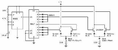
Traffic Lamps Circuit
Traffic lamps circuit controls 6 units LEDs (red, yellow, green). Time sequence followed CD4017 CMOS IC as a decade counter and NE 555 timer IC. counter output 1 to 4 using 4 diodes so that the (red-north / south) and (green) 4 LED is the first timers. counter to 5 (foot 10) turn (yellow) and (red). The counter 6 to 9 is also controlled by the 4 diodes (red and yellow). The time period for the red and green LED 4 times longer than the yellow LED. To adjust the speed by varying the 47K ohm resistor value. Eighth zener diode 4148 is divided into two parts and each got 4 input OR gate of IC CD 4017.
Component of traffic lamps Circuit :
- 4017 1 IC CD
- IC 555 NE 1
- red LED 2
- Yellow LED 2
- 2 green LEDs
- Jumper link
- Transistor C 9016 4
- 4148 8 zener diode
- 2 180-ohm resistor
- 1 47Kohm Resistor
- Resistor 1Kohm 1
- electrolit condensator a 10uf 50V


